Grounding Solar Panels: What Each Part Actually Does

Here’s the thing about grounding solar panels that took me longest to get straight, so I’ll lead with it: a ground rod does not protect you from an electrical fault.
I know. It’s called a ground rod. You drive it into the dirt, you bolt a wire to it, it feels like the safety thing is handled.
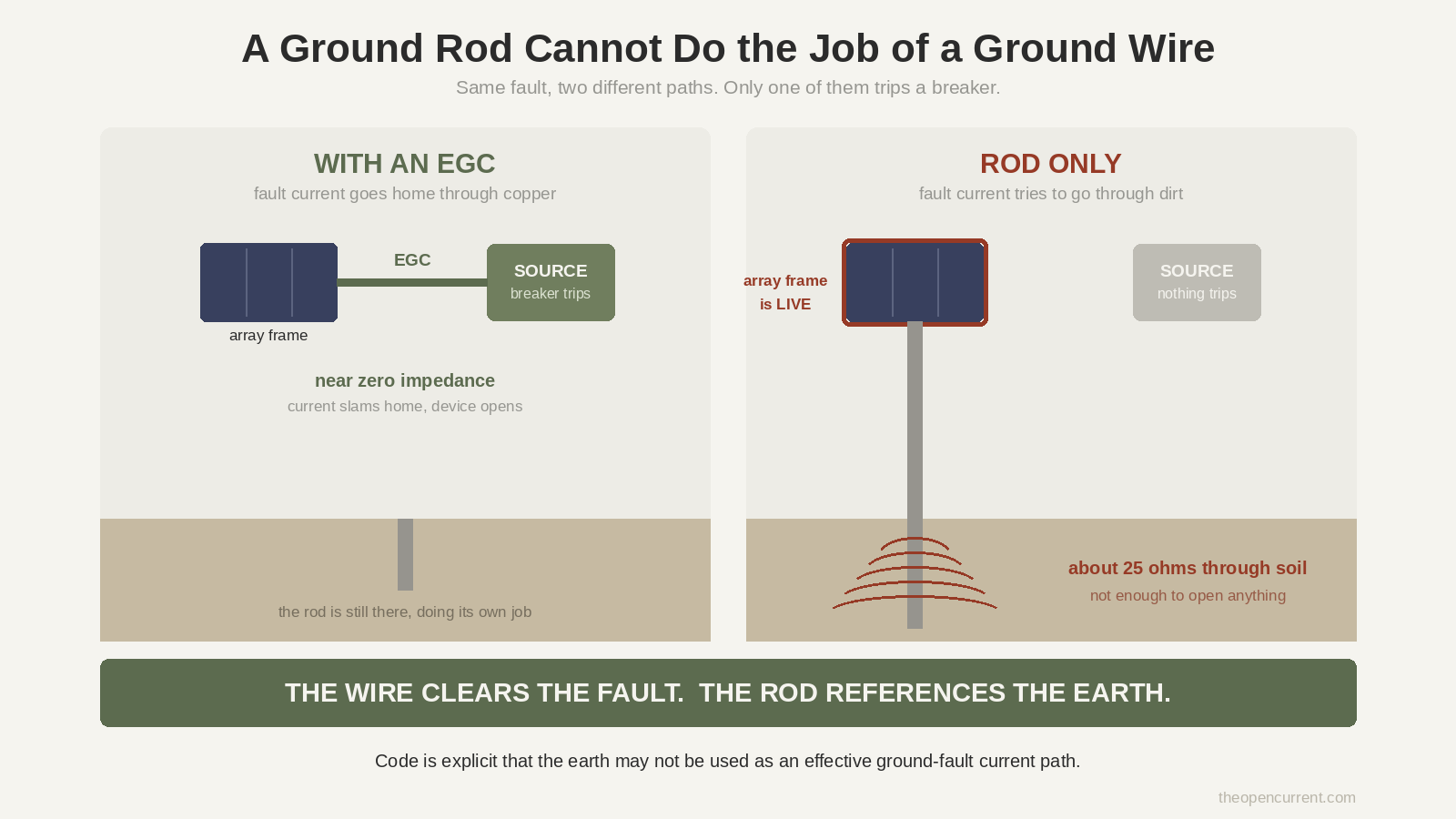
Except dirt is a lousy conductor. A code-compliant ground rod might sit at 25 ohms to earth. If a hot conductor inside a panel touches the aluminum frame, 25 ohms isn’t anywhere near low enough to pull that frame back down to zero volts. The frame sits there energized, a trickle of current wanders off into the soil, nothing trips, and the first thing that tells you there’s a problem is you, touching it.
The thing that actually saves you in that scenario is a wire. A continuous copper path from the panel frame all the way back to your system’s ground, low enough impedance that fault current slams home and pops a breaker.
The rod does a different job. Both matter. They are not interchangeable, and mixing them up is where most of the confusion around solar panel grounding lives.
Quick flag before we go further. This article explains what the pieces do and why, so you can understand your own system and have a useful conversation with an electrician or inspector. It is not an installation guide. Grounding is a shock hazard topic and I’m not going to pretend a blog post replaces someone who does this for a living.
There are two different things called grounding
This is the single most useful distinction on the page, and once you’ve got it a lot of confusing advice suddenly makes sense.
Equipment grounding is bonding together all the metal that isn’t supposed to carry current. Panel frames, racking rails, enclosures, conduit. All of it wired together and connected back to your system ground, so that if any of it accidentally becomes live, fault current has a fast way home. This is required on basically every PV system in the US under NEC Article 690.
System grounding is deliberately connecting one of the actual current-carrying conductors to earth. Different thing entirely, and whether you do it depends on your equipment.
So when somebody asks “do I need to ground my solar panels,” there are two correct answers and they’re answering different questions. The equipment grounding answer is yes, nearly always. The system grounding answer is: depends on your inverter, and don’t improvise.
Original diagram. Reuse it with a link to theopencurrent.com.
What the equipment grounding conductor actually does
NEC 690.43 is the one that requires exposed non-current-carrying metal, so your module frames, mounting system, enclosures and associated equipment, to be bonded and connected to an equipment grounding conductor.
Couple of practical things fall out of that.
The hardware matters. Whatever you use to bond module frames has to be listed for the job. UL 2703 is the standard covering mounting systems, clamps and ground lugs for flat-plate PV modules. The reason it matters is that anodizing is a dielectric coating, so an ordinary screw through an anodized rail is not necessarily making an electrical connection at all. Listed bonding hardware is designed to bite through it. Random hardware store fasteners are not.
Sizing comes from a table, not vibes. 690.45 points you at Table 250.122, sized on the rating of the overcurrent device protecting the circuit. Worth knowing that EGCs don’t get upsized for voltage drop the way current-carrying conductors sometimes do, because they’re not carrying current in normal operation.
And it runs with the array wiring. If you’ve read the series vs parallel guide you already know the drill on running conductors out to a ground mount. The ground wire goes with them. Code does allow EGCs to be run separately from the PV conductors within the array, but once the circuit conductors leave the array’s vicinity there are rules about it.
What the ground rod is actually for
Rods handle the earth reference and the surge energy. Lightning, nearby strikes, general overvoltage. That’s the job.
The specs, and these are worth knowing because they’re checkable:
Eight feet minimum, per NEC 250.52(A)(5), and 5/8 inch copper-bonded steel is the standard residential rod.
Driven to full depth. 250.53(G) wants the full 8 feet in the soil. If you hit rock, the permitted alternatives are driving it at an angle up to 45 degrees or laying it in a trench at least 30 inches deep. What you cannot do is cut it shorter to make it fit, which I suspect happens more than anyone admits.
Two rods, basically always. 250.53(A)(2) says a single rod has to be supplemented by a second one. There’s an Exception letting you use just one if it tests at 25 ohms or less to earth, but testing that needs a proper ground resistance tester, which is not a thing sitting on the shelf at your local hardware store. So most electricians drive two from the start, and once the second one is in, the code doesn’t ask you to test anything.
Six feet apart minimum, per 250.53(A)(3). And here’s a nuance worth having: six feet is the legal floor, not the sweet spot. Each rod has a sphere of influence in the soil, and when two spheres overlap the pair works worse than it could. Rule of thumb I’ve seen from engineers is spacing them about twice the rod length. Nobody’s stopping you going further apart, and out on a rural property you’ve usually got the room, so why not.
Why grounding solar panels gets such different answers
Right, this is the good stuff, and it took me four passes through the code to spot it.
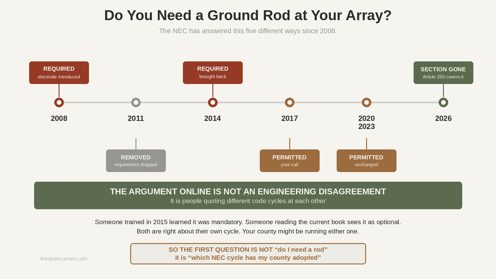
If you go looking for whether you need a ground rod at your array specifically, you’ll find people flatly contradicting each other. Some say it’s mandatory. Some say it’s optional. Some say it’s actively a bad idea. It looks like a mess.
It isn’t. They’re each correct about the code cycle they learned.
| NEC cycle | Electrode at the array |
|---|---|
| 2008 | Introduced, required |
| 2011 | Removed |
| 2014 | Back again, and required |
| 2017 | Changed to permitted, not required |
| 2020 and 2023 | Still permitted, not required |
| 2026 | Section deleted entirely |
Five changes in eighteen years. The 2026 deletion happened because the Code Making Panel decided the PV-specific section was restating things Article 250 already covered, with less detail, and was creating conflicts between the two articles.
So the guy who trained in 2015 telling you a rod at the array is mandatory is right about 2014. The guy reading the current book telling you it’s optional is right about now. And your county might be running either one, because code adoption lags publication by years and varies by state.
Which makes “what code cycle are you on” the actual first question, not “do I need a rod.” Ask your AHJ. It’s a free phone call and it settles an argument that’s been running on forums for a decade.
One thing that hasn’t changed across any of those cycles: a support structure for a ground-mounted array is permitted to be considered a grounding electrode itself if it meets 250.52. So if your posts are set deep in concrete, you may already have one and not know it.
Original diagram. Reuse it with a link to theopencurrent.com.
The bonding rule, and the exception inside it
Standard advice is that all your grounding electrodes get bonded together into one system. That’s 250.50, and it’s true for the electrodes that make up your grounding electrode system.
But there’s a specific carve-out that matters here. 250.54 covers auxiliary grounding electrodes, and it says they’re permitted to be connected to the equipment grounding conductors and are not required to comply with the bonding requirements of 250.50, or the 25 ohm resistance requirement.
So an extra rod at your array isn’t automatically part of your grounding electrode system, and code doesn’t force you to tie it in.
What 250.54 does not let you off the hook for, and this is the sentence that matters: the earth shall not be used as an effective ground-fault current path. A rod connected to equipment can give you a local ground reference. It can never stand in for the EGC.
Plenty of PV people recommend bonding auxiliary electrodes anyway, to avoid differences of potential between two bits of metal you might touch at the same time. I’d call that sound engineering rather than a code requirement, and it’s worth raising with whoever signs off your install.
Off grid changes the picture
Grid tied, there’s a utility service, a main panel and an existing grounding electrode system already sitting there waiting to be connected to. Off grid you have none of that, and three things change as a result.
Your inverter becomes the source. In a grid-tied house, the neutral to ground bond lives at the service panel. Off grid, your inverter is the source of power, so that’s where the bond belongs, at the inverter or the first panel it feeds.
And there has to be exactly one of them. Here’s the trap, and it catches a lot of people with a cabin setup: most generators already have neutral bonded to the frame at the unit. So the moment you add a genset to an inverter-based system you’ve potentially got two bonds, which means neutral current sharing paths it shouldn’t. How you handle that depends on your specific transfer switch and inverter, and it’s genuinely one to hand to a professional rather than guess at.
Cheap inverters are floating neutral and can’t be bonded at all. Downstream GFCI breakers don’t behave properly on those either, which is the sort of thing you find out at the worst moment.
The DC side is messy by design. Most charge controllers and inverters ship with the negative bonded to the chassis. One electrician on the Mike Holt forum has strong opinions about that being a manufacturer choice rather than a good idea, because it can force normal DC load current onto bonding conductors. Either way, it’s a reason not to start adding your own DC grounds without knowing what your equipment already does internally.
The honest summary: off grid grounding is more involved than grid tied, not less, precisely because there’s no service panel doing half the thinking for you. If you’re planning the whole system, the off-grid solar guide covers how the pieces fit together.
Lightning, and an expectation that needs resetting
If you’re putting a ground mount up on a rural property, you’re thinking about lightning. Fair enough. But there’s a hard truth here that I’d rather say plainly than let you find out expensively.
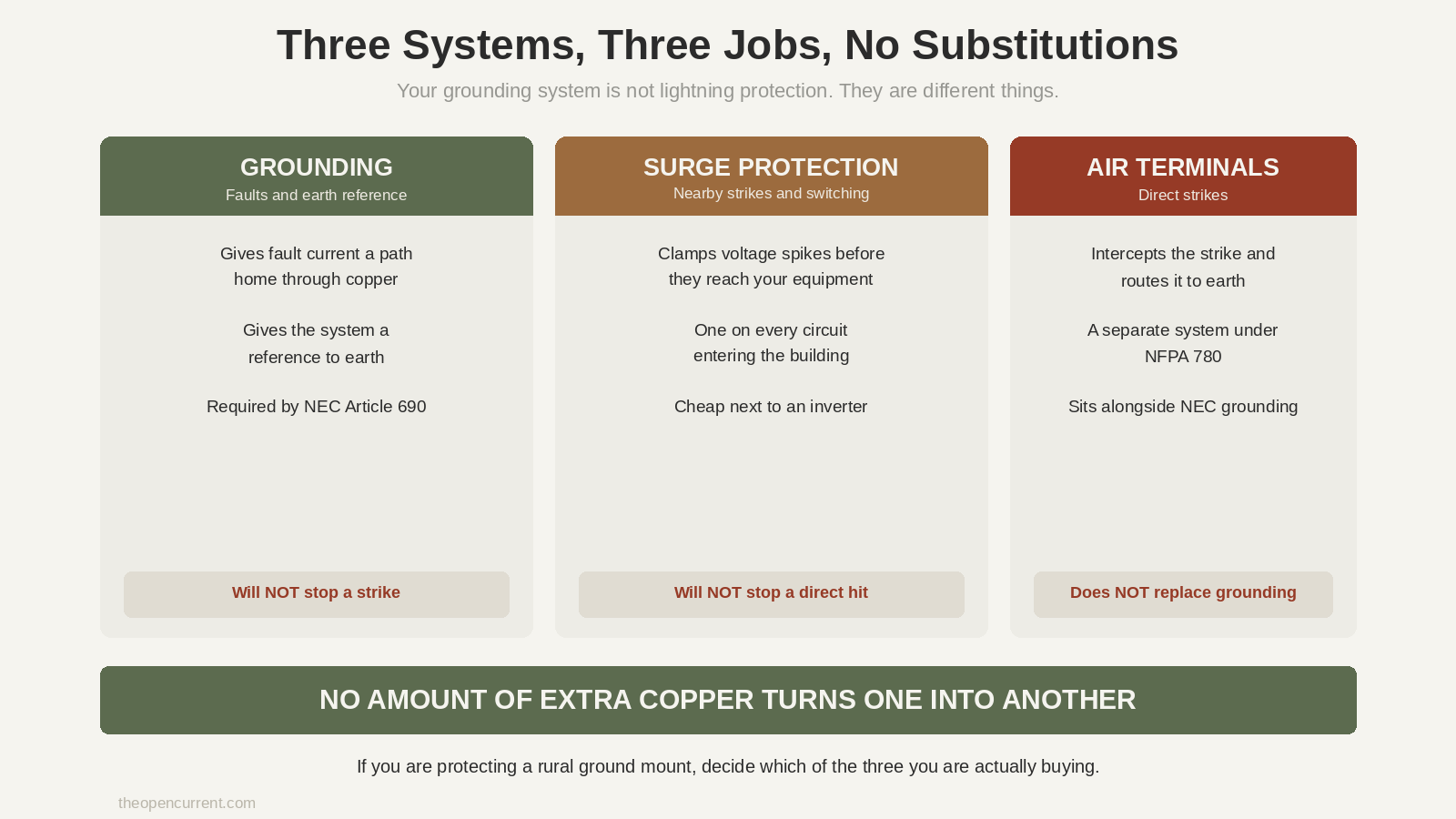
Your grounding system will not stop a direct strike. It isn’t designed to and no amount of extra copper changes that. As one forum contributor puts it, the electrical grounding system simply isn’t capable of handling a direct lightning strike no matter how many electrodes you stick in the earth.
What you actually have is three separate things doing three separate jobs:
- Grounding gives fault current a path and gives the system an earth reference
- Surge protective devices clamp the voltage spikes from nearby strikes and switching events. Advice is one on every circuit entering the building
- Direct strike protection means air terminals, which is a whole separate system under NFPA 780. It sits alongside NEC grounding, it doesn’t replace it
One detail I liked, from a long-time contributor on the solar-electric forum: lightning will follow a 6 AWG conductor maybe ten to twenty feet before it decides to jump to something with lower impedance, and a sharp right angle bend in the wire is enough to make it leave early. So keeping ground runs short and the bends gentle isn’t fussiness. It’s the entire mechanism.
Also worth knowing: ground rods belong outside the building. You’re trying to get lightning energy into the earth and away from the structure, not invite it in through the wall.
Original diagram. Reuse it with a link to theopencurrent.com.
What to ask, and who to ask
Four things worth a phone call before you buy hardware or bury anything.
Ask your AHJ which NEC cycle your county has adopted. Everything above about the array electrode hinges on it, and it’s a thirty second answer.
Ask whether they want an electrode at a ground mount, and whether they want it bonded. The code permits either way in recent cycles. Your inspector may well have a preference, and finding out now beats finding out at inspection.
Ask about ground fault protection for your specific configuration. Requirements vary by code cycle and by whether your inverter has it built in. Modern gear usually does. Older or unusual setups, less predictable.
Ask an electrician about the neutral to ground bond if you’ve got a generator. Two bonds is a real hazard and the correct answer depends on the equipment you own. This is the one I’d least want somebody guessing at based on a forum post.
And a general one: if you want to read the actual code rather than people’s summaries of it, NFPA publishes the NEC for free reading online. You have to make an account, but it costs nothing, and reading 250.53 yourself beats reading my version of it.
Common ways this goes wrong
Treating a rod as the ground. Covered at the top, but it’s the big one. The rod is not the fault path.
Assuming anodized rails bond themselves. That anodized layer is a dielectric coating, and an ordinary fastener through it may make a mechanical connection without making an electrical one. Listed bonding hardware exists for exactly this reason.
Adding a system ground to equipment that doesn’t want one. Modern transformerless inverters generally establish their own reference and detect faults electronically. Bolting your own DC ground on can defeat the fault detection. Check what your equipment does before you improve it.
Working from a section number that has moved. The 25 ohm rule used to live at 250.56 and now sits at 250.53(A)(2). 690.41 has been retitled between cycles. If you’re reading anything written more than a few years ago, including your own notes, check the number still points where you think it does.
Thinking more rods equals more safety. Multiple earth connections in different places can give a nearby strike’s ground gradient more routes into your equipment. This is a genuine engineering debate rather than a settled answer, which is why it’s on the ask-your-inspector list rather than in the tell-you-what-to-do list.
FAQ
Do solar panels need to be grounded? The metal parts, yes. NEC Article 690 requires module frames, racking, enclosures and associated metal to be bonded to an equipment grounding conductor. Whether you also need a system ground, meaning a current-carrying conductor tied to earth, depends on your inverter, and modern transformerless units generally don’t want one.
Is a ground rod enough? No. A rod gives you an earth reference and a path for surge energy. It cannot clear a fault, because soil resistance is far too high. Code is explicit that the earth may not be used as a fault current path.
Do I need a ground rod at my ground-mounted array? Depends on your code cycle. It was required under the 2014 NEC, changed to permitted in 2017, and the section was removed altogether in 2026. Ask your AHJ which cycle applies where you are.
How deep does a ground rod need to go? Eight feet, in full contact with soil. If rock stops you, permitted alternatives are driving at up to 45 degrees or laying it in a 30 inch trench. You can’t shorten it.
Why two ground rods? Because 250.53(A)(2) requires a single rod to be supplemented unless it tests at 25 ohms or less, and testing needs equipment most people don’t have. Two rods six feet apart satisfies the code without testing anything.
Does grounding protect against lightning? Not a direct strike. Grounding handles faults and gives surges somewhere to go. Surge protective devices handle surges. Direct strike protection is air terminals under NFPA 780, which is a separate system entirely.
Does an off grid system still need grounding? Yes, and arguably it needs more thought, because there’s no service panel already establishing the grounding electrode system and the neutral to ground bond for you. Your inverter takes that role, and adding a generator complicates it.
Where to go next
- Solar panels in series vs parallel. How you wire the array, and why the ground wire runs with the rest of it.
- Off-grid solar kit buying guide. What’s in the box, and what isn’t.
- Free solar battery calculator. Size the bank before you size anything else.